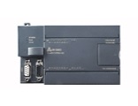
Products > Control Systems > PLC > PLC300 Series > CPU
PLC300-C34GT
| Product Code | PLC300-C34GTD | PLC300-C34GTA |
| Description | CPU, DC/DC/DC | CPU, AC/DC/Relay |
|
Physical Size |
||
| Dimensions (W×H×D) | 137mm × 80mm × 62mm | 137mm × 80mm × 62mm |
| Power loss (dissipation) | 7 W | 10 W |
|
Power Supply |
||
| Line voltage-permissible range | 20.4 to 28.8VDC | 85 to 264 VAC,47 to 63 Hz |
| Input current CPU only / max load | 110/700 mA at 24 V DC |
30/100 mA at 240 V AC 60/200 mA at 120 V AC |
| In rush current (maximum) | 10 A at 28.8 V DC | 20A at 264 V DC |
| Isolation (input power to logic) | Not isolated | 1500V AC |
| Hold up time (from loss of input power) | 10 ms at 24 V DC | 80 ms at 240 V AC, 20ms at 120 V AC |
| Internal Fuse, not user-replaceable | 2 A, 250 V, Slow Blow | 2 A, 250 V, Slow Blow |
| +5 V DC power for Expansion I/O (max) | 660mA | 660mA |
|
24 V DC Sensor Power Output |
||
| Voltage range | 15.4 to 28.8 V DC | 20.4 to 28.8 V DC |
| Maximum current | 280 mA | 280 mA |
| Ripple noise(maximum) | Same as input line | Less than 1 V peak to peak |
| Current limit | 600mA | 600mA |
| Isolation (sensor power to logic circuit) | Not isolated | Not isolated |
|
CPU Features |
||
| On-board digital inputs | 14, 24 V DC | 14, 24 V DC |
| On-board digital outputs | 10, 24 V DC | 10, Relay |
| Program memory size | 12KB base memory, can be expanded to 16KB | |
| Data block size | 8KB base memory, can be expanded to 108KB | |
| Stored permanently | 8KB | |
| Backed by super capacitor or battery | 8KB | |
|
High-speed counters (32 bit value) |
||
| Total | 6 High-speed counters | |
| Single phase counters | 6, each at 30 KHz clock rate | |
| Two phase counters | 4, each at 30 KHz clock rate | |
| Pulse outputs | 2 at 20 KHz pulse rate | |
| Analog adjustments | 2 with 8 bit resolution | |
| Timed interrupts | 2 with 1ms resolution | |
| Edge interrupts | 4 edge up and/or 4 edge down | |
| Selectable input filter times | 7 ranges from 0.2ms to 12.8ms | |
| Pulse catch | 14 pulse catch inputs | |
| Number of expansion I/O Modules | 7 modules | |
| Maximum digital I/O | 256 points (128 inputs / 128 outputs) | |
| Maximum analog I/O | 64 points (32 inputs / 32 outputs) | |
| Internal memory bits | 256 bits | |
| Stored permanently on power down | 112 bits | |
| Backed by super capacitor or battery | 256 bits | |
| Timers Total | 256 timers | |
| Backed by super capacitor or battery | 64 timers | |
| 1ms | 4 timers | |
| 10ms | 16 timers | |
| 100ms | 236 timers | |
| Counters total | 256 counters | |
| Backed by super capacitor or battery | 256 counters | |
| Boolean execution speed | 0.15μs per instruction | |
| Float execution speed | 8μs per instruction | |
| Super capacitor data retention time | 100 hours, typical | |
|
Onboard Communication |
||
| Communication Interface | 2, PORT0 for PPI/MPI in RS485 and RS232, FPROT for freeport in RS485 and RS232 | |
| Isolation(external signal to logic circuit) | Not isolated | |
| PPI/MPI baud rates | 9.6, 19.2 and 187.5 kbaud | |
| Freeport baud rates | 0.3, 0.6, 1.2, 2.4, 4.8, 9.6, 19.2 and 38.4 kbaud | |
|
Maximum cable length per segment |
||
| Up to 38.4 kbaud | 1200 m | |
| 187.5 kbaud | 1000 m | |
|
Maximum number of stations |
||
| Per segment | 32 stations | |
| Per network | 126 stations | |
| Maximum number of masters | 32 masters | |
| PPI master mode (NETR/NETW) | Yes | |
| MPI connections | 8 total, 2 reserved:1 for PG and 1OP | |
|
Input Features |
||
| Number of integrated inputs | 14 inputs | |
| Input type | Sink / Source (IEC Type 1 sink) | |
|
Input Voltage |
||
| Maximum continuous permissible | 30 V DC | |
| Surge | 35 V DC for 0.5 s | |
| Rated value | 24 V DC at 4 mA, nominal | |
| Logic 1 signal (minimum) | 15 V DC at 2.5 mA, minimum | |
| Logic 0 signal (maximum) | 5 V DC ata 1mA, maximum | |
|
Isolation (Field Side to Logic Circuit) |
||
| Optical isolation (Galvanic) | 500 V AC for 1 minute | |
| Isolation groups of | 8 points | |
|
Input Delay Times |
||
| Filtered inputs and interrupt inputs | 0.2 to 12.8 ms, user-selectable | |
| HSC Clock Input Rate | ||
|
Single Phase |
||
| Logic 1 lever = 15 to 30 V DC | 20 KHz, maximum | |
| Logic 1 lever = 15 to 26 V DC | 30 KHz, maximum | |
|
Quadrature |
||
| Logic 1 lever = 15 to 30 V DC | 10 KHz, maximum | |
| Logic 1 lever = 15 to 26 V DC | 20 KHz, maximum | |
|
Connection of 2 Wire Proximity Sensor (Bero) |
||
| Permissible leakage current | 1 mA, maximum | |
|
Cable Length |
||
| Unshielded (not HSC) | 300 m | |
| Shielded | 500 m | |
| HSC inputs, shielded | 50 m | |
|
Number of inputs ON Simultaneously |
||
| 40℃ | 14 | |
| 50℃ | 14 | |
|
Output Feature |
||
| Number of integrated outputs | 10 outputs | 10 outputs |
| Output type | Solid State-MOSFET | Relay, dry contact |
|
Output voltage |
||
| Permissible range | 20.4 to 28.8 V DC | 5 to 30 V DC or 5 to 250 V AC |
| Rated value | 24 V DC | - |
| Logic 1 signal at maximum current | 20 V DC, minimum | - |
| Logic 0 signal with 10 kohm load | 0.1 V DC, maximum | - |
|
Output Current |
||
| Logic 1 signal | 0.75 A | 2 A |
| Number of output groups | 2 | 3 |
| Number of output ON (maximum) | 10 | 10 |
| Per group-horizontal mounting (maximum) | 5 | 4/3/3 |
| Per group-vertical mounting (maximum) | 5 | 4/3/3 |
| Maximum current per common/group | 3.75 A | 8 A |
| Lamp load | 5 W | 30 W DC/200 W AC |
| ON state resistance (contact resistance) | 0.3 ohm | 0.2 ohm, maximum when new |
| Leakage current per point | 1 0 μA, maximum | - |
| Surge current | 8 A for 100 ms, maximum | 7 A with contacts closed |
| Overload protection | No | No |
|
Isolation |
||
| Optical isolation (galvanic) | 500 V AC for 1 minute | - |
| Isolation resistance | - | 100 Mohm, minimum when new |
| Isolation coil to contact | - | 1500 V AC for 1 minute |
| Isolation between open contacts | - | 750 V AC for 1minute |
| In group of | 5 points | 3 points |
|
Inductive Load Clamping |
||
| Repetitive energy dissipation | 1W, all channels | - |
| Clamp voltage limits | L+ minus 48V | - |
|
Output Delay |
||
| Off to On | 15μs, maximum | - |
| On to Off | 100μs, maximum | - |
|
Switching Frequency(pulse train outputs) |
||
| Q0.0 and I0.0 | 20 KHz, maximum | 1 Hz, maximum |
|
Relay |
||
| Switching delay | - | 10 ms, maximum |
| Lifetime mechanical (no load) | - | 20,000,000 open / close cycles |
| Lifetime contacts at rated load (2A) | - | 300,000 open/close cycles |
|
Cable Length |
||
| Shielded | 500 m | 500 m |
| Unshielded | 150 m | 150 m |
Accessories
1. Programmable Cable
2. Battery
3. Memory Card